Clair’s solution to India’s largest integrated producer of Ferro Alloy

Introduction:

We are happy to share our experience with India’s largest integrated producer of Ferro Alloys. We received a request for the manufacture, design and installation of the heat exchanger at the client’s site in Odisha.

Well the background is as follows:-

  • The Forced Draft (FD) cooler is tubular convective type Heat Exchanger used for cooling of hot gases. FDC is a modern addition to an array of Pollution Control Equipment. It is majorly used to substantially reduce the temperature of gas where high temperature can damage the equipment
  • With the use of banks of tubes placed vertically, hot gases is passed through inside of the tubes to achieve desired temperature drop
  • In Ferro alloy plants the outlet gases from sub merged arc furnace are at approximately 500 to 600 °C. These flue gases cannot be let out to atmosphere as it is and are to be de-dusted. Hence, it is mandatory to provide dust collecting system
  • The major problem of providing the dust collecting system is the temperature of the flue gases and it becomes necessary to cool the kiln exhaust gases to around 120 to 150 °C
  • The best way to accomplish this task is to have air to gas heat exchanger. Although dilution with ambient air or water spray etc. are available for the heat exchanger
  • Air to gas force draft heat exchanger are the simple, economical and best suited system

Data/ Table:

Table 1: Technical Specifications of the FD Cooler

Sl. NO.DescriptionUnitsValue
1.Gas volume at normal conditionsNm3/h2,50,000
2.Gas temperature at FD Cooler inlet0C325
3.Gas inlet volume at operating temperature (common)m3/h5,47,619
4.Type of pass arrangement Series
5.No. of passes for flue gasNo.3
6.Gas temperature at FD Cooler outlet0C120
7.Gas outlet volume at operating temperature (common)m3/h3,59,890
8.Dust concentration in gasesgm/m38
9.Tube diameter and lengthmm ¯X mm lg.141.3 OD/ 2.8 mm thick X 12000
10.Number of tubes in each passNo.

Pass – 1 : 456

Pass – 2 : 361

Pass – 3 : 323

11.Total number of tubesNo.1,140
12.Total heat transfer aream26,076.2
13.Tube material IS 1239
14.Pressure drop across the FD CoolermmWC100 to 125
15.Cooling air volume per passm3/h5,00,000
16.Cooling air inlet temperature0C48 (Max)
17.Total Number of cool air fans per passNo.4
18.Capacity of cool air fans (each)m3/h

1,25,000

@ 45 mm WC

19.Motor capacities of cool air fans with FRP blades for impellerskW30.0

Observations:

Clair took up the challenge and following solution was proposed and implemented:

  • The provided FD Cooler is Air to Air FD Cooler with 3 No. passes installed in series arrangement
  • Since the Air to Air heat transfer is very low compared to any other heat exchange, the care has been taken to select appropriate overall heat transfer coefficient
  • Since the flue gases contain the dust, the probable dust coating on tubes is also considered in deciding the heat transfer area required
  • The tube diameter selected is 135.7 mm ID considering the dust concentration of flue gases and the large diameters avoids the problem of choking of the tubes
  • The gas velocities inside the tubes has been considered taking into account the abrasive nature of the dust
  • Three pass FD Cooler is designed for efficient cooling of the gases
  • Gas flow in tubes in every pass with appropriate velocities to avoid dust deposition in the tubes.
  • Top entry for the first pass is designed for uniform gas distribution in the tubes
  • Tubes are arranged in triangular pitch for better contact between cool air and tubes
  • Axial fans are selected as cool air fans for better heat transfer
  • Hoppers are provided for each pass. The dust from the hoppers is continuously transported via dust disposal system with Knife edge gate valve, dome valves & conveying system of Mecgale make

Clair successfully implemented and commissioned the installation of New FD Cooler in 2018 for capacity of 2,50,000 Nm3/Hr at 325 o C

Picture:
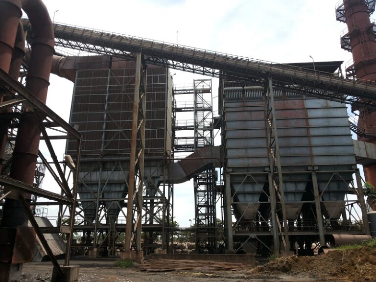
Figure 1: Heat Exchanger & Bag Filter setup at a Client site

Copyright © 2022 Clair Engineers Pvt Ltd.