Pushing ESP boundaries
Introduction:
We have had an opportunity to work with another reputed cement manufacturer located in Rajasthan. The clinker cooler gases were led into an ESP, which was originally designed for achieving an emission of ≤ 50 mg/Nm3. The client had to meet the recent norms of ≤ 30 mg/Nm3 emission from the ESP. The client was also proposing to install a WHRS system after the clinker cooler, where the gases from clinker exhaust will be led into the WHRS and the gases from the WHRS outlet will be taken into the ESP for control of particulate matter. The existing ESP was designed for a volume of 4,87,200 m3/h at an inlet temperature of 280 0C. The existing ESP is a 3 field ESP, with 14.5 m collecting electrode height and a gas velocity of 0.69 m/s.
The ESP was not performing as per the designed emission norms due to some internal problems. Clair was handed with the task to achieve an emission of ≤ 30 mg/Nm3 for the conditions specified in Table 1 with the installation of WHRS.
Data/ Table:
Table 1: Design parameters of Clinker Cooler ESP
Sl. No. | Description | Unit | Value |
A | Case 1 | WHRS OFF | |
Gas Volume | m3/hr | 4,87,200 | |
Operating Temperature | 0C | 280 | |
B | Case 2 | WHRS ON | |
Gas Volume | m3/hr | 2,20,000 | |
Operating Temperature | 0C | 120 | |
C | Case 3 | WHRS ON | |
Gas Volume | m3/hr | 2,65,000 | |
Operating Temperature | 0C | 170 |
Observations:
Clair took up the challenge and following solution was proposed and implemented:
Clair successfully implemented and commissioned the installation of New ESP in parallel to the existing ESP to achieve the emission of ≤ 30 mg/Nm3. Since it’s commissioning the clinker cooler ESP is operating successfully as per the designed emission norms.
Pictures:

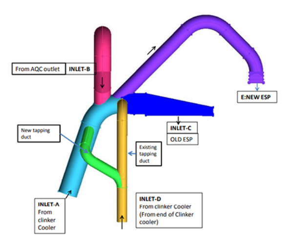
Figure 1: Inlet Ducting Arrangement to the Existing ESP and New Parallel ESP


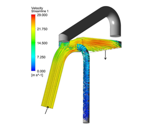
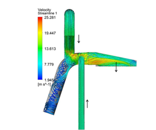
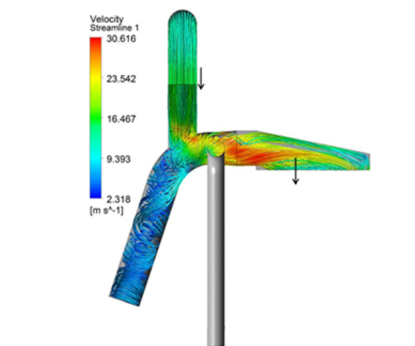
Figure 2: The Design parameters of Clinker Cooler ESP as per Table 1.