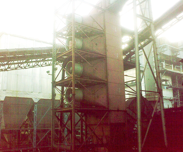
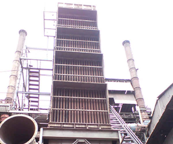
Shell and Tube type Heat Exchanger
Introduction:
We have played an important part in the design, manufacture and installation for an important client located in Raipur, Madhya Pradesh. The requirement was for a 9.0 MVA Ferro Alloy Furnace for the reduction of the Exhaust Gases.
Our client had been facing the problem in the furnace because the Gas Cleaning Plant (GCP)had temperature reduction done by FD cooler, but the working efficiency was very poor and we at Clair proposed to assess the performance of the GCP.
On visiting the site, the basic type of application and product line was understood that is given in Table 1 while, the technical specifications are mentioned in Table 2.
There were many factors on which we proposed the following:-
Data/ Table:
Table 1: Basic Details collected during Visit
S.No | Particulars | Description |
1. | Dust Details | Fine Particles generated during production of Ferro Alloy Mainly Oxides and Chlorides |
2. | Product | FeMn /SiMn |
3. | Fuel Used in the Furnace | Coal + Coke |
Table 2: Technical Specifications Of Heat Exchanger
S.No | Description | Units | Value |
1. | Gas volume at normal conditions | N.cu.m/hr | 74,000 |
2. | Gas temperature at Heat Exchanger inlet | o C | 250 – 280 (normal opg), 350 (peak for ½ hr) |
3. | Gas inlet volume at operating temperature | cu.m/hr | 1,40,000 |
4. | Gas temperature at Heat Exchanger outlet | o C | 120 to 130 |
5. | Gas outlet volume at operating temperature | cu.m/hr | 1,07,800 |
6. | Dust concentration in gases | gms/cu.m | 5 |
7. | Number of passes for flue gas | Nos. | 1 |
8. | Tube diameter and length | mm ¯X mm lg. | 108 OD X 10460 |
9. | Total number of tubes | Nos. | 280 |
10. | Total heat transfer area | sq.m | 956 |
12. | Tube material | Not Applicable | MS ERW |
13. | Pressure drop across the Heat Exchanger | mm WC | 40 |
14. | Cooling air volume | cu.m/hr | 2,00,000 |
15. | Cooling air inlet temperature | o C | 35 |
16. | Number of cool air fans | Nos. | 4 |
17. | Capacity of cool air fans | cu.m/hr | 50,000 @ 75 mm WC |
18. | Motor capacities of cool air fans | HP | 30 |
19. | Total weight of Heat Exchanger with tubes | MT | 60 approx. |
Observations:
Clair took up the challenge and following solution was proposed and implemented:
Clair successfully implemented and commissioned the installation of NewShell and Tube type Heat Exchanger in 2018with emissions of 80,000 Nm3/Hr at 280oC.
Pictures:

