Stepping-up with ESP success
Introduction:
A reputed client located in Gujarat, has an existing ESP of Flakt make commissioned in the year 1993. The ESP was installed for clinker cooler application and was designed for achieving an outlet emission of ≤ 100 mg/Nm3. With the stringent emission norms introduced by the Central Pollution Control Board (CPCB), the client approached Clair to retrofit the ESP for achieving an outlet emission of ≤ 25 mg/Nm3 in the year 2007. The existing ESP is a 3 field ESP designed for a gas volume of 4,80,000 m3/h (Table 1). Client suggested to add an additional field (4th field) to achieve the outlet emission of ≤ 25 mg/Nm3.
Data/ Table:
Table 1: Existing ESP Parameters
Sl. No. | Description | Unit | Value |
1 | Gas Volume | Nm3/hr | 4,80,000 |
2 | Operating Temperature | 0C | 280 |
3 | Inlet dust load | gm/Nm3 | 41 |
4 | Gas velocity | m/s | 0.79 |
5 | Collecting plate height | m | 14 |
6 | No. of gas passages | No. | 30 |
7 | Specific collection area (SCA) | m2/m3/s | 70.9 |
8 | Outlet dust load | mg/Nm3 | ≤ 100 |
Table 2: Retrofit ESP Parameters
Sl. No. | Description | Unit | Value |
1 | Gas Volume | Nm3/hr | 3,80,000 |
2 | Operating Temperature | 0C | 160 |
3 | Inlet dust load | gm/Nm3 | 41 |
4 | Gas velocity | m/s | 0.63 |
5 | Collecting plate height | m | 14 |
6 | No. of gas passages | No. | 30 |
7 | Specific collection area (SCA) | m2/m3/s | 89.5 |
8 | Outlet dust load | mg/Nm3 | ≤ 25 |
Observations:
The client also had plans to install a Waste heat recovery (WHR) system before the ESP to utilize the available heat. Based on the installation of WHRS, the new gas volume would be 3,80,000 m3/h at temperature of 160 0C. Based on the new information made available and inspection done on the existing ESP, Clair set out to retrofit the ESP for achieving an outlet emission of ≤ 25 mg/Nm3.
Clair took up the challenge to retrofit the ESP to achieve the requested outlet emission. The first approach was to inspect the existing ESP and determine the healthiness of the equipment. Based on inspection, following steps were taken:
Clair proposed to retrofit the ESP by utilizing the existing 3 fields only, without adding any new field for the volume of 3,80,000 m3/h (Table 2). CFD analysis was performed to achieve uniform gas distribution in the ESP. Based on the CFD analysis, the complete GD screen arrangement was changed. New inlet plenum and guide vanes were provided to distribute the gas flow uniformly. New collecting and discharge electrodes were provided in the 3 fields, wherever the electrodes were worn out or damaged. Alignment of the complete collecting & discharge electrodes assembly was performed. Existing TR sets were replaced with 3 phase TR sets with advanced controllers. The retrofit was completed and the ESP was put into operation and was able to successfully achieve the outlet emission of ≤ 25 mg/Nm3.
Pictures:

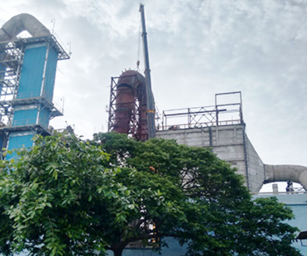
Figure 1: Our ESP Retrofit during the installation phase.
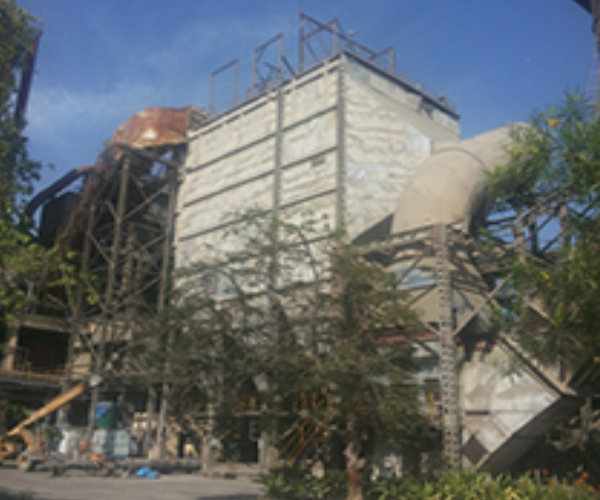
Figure 2: Our ESP Retrofit post commissioning
